Objective
We built a mobile robot that receives commands from a base station. The base station sends commands corresponding to detected hand gestures that it analyzes using OpenCV from a PiCamera input. The mobile robot also relies on the use of an accelerometer to correct errors in motion and an ultrasonic sensor to prevent collisions.
Introduction
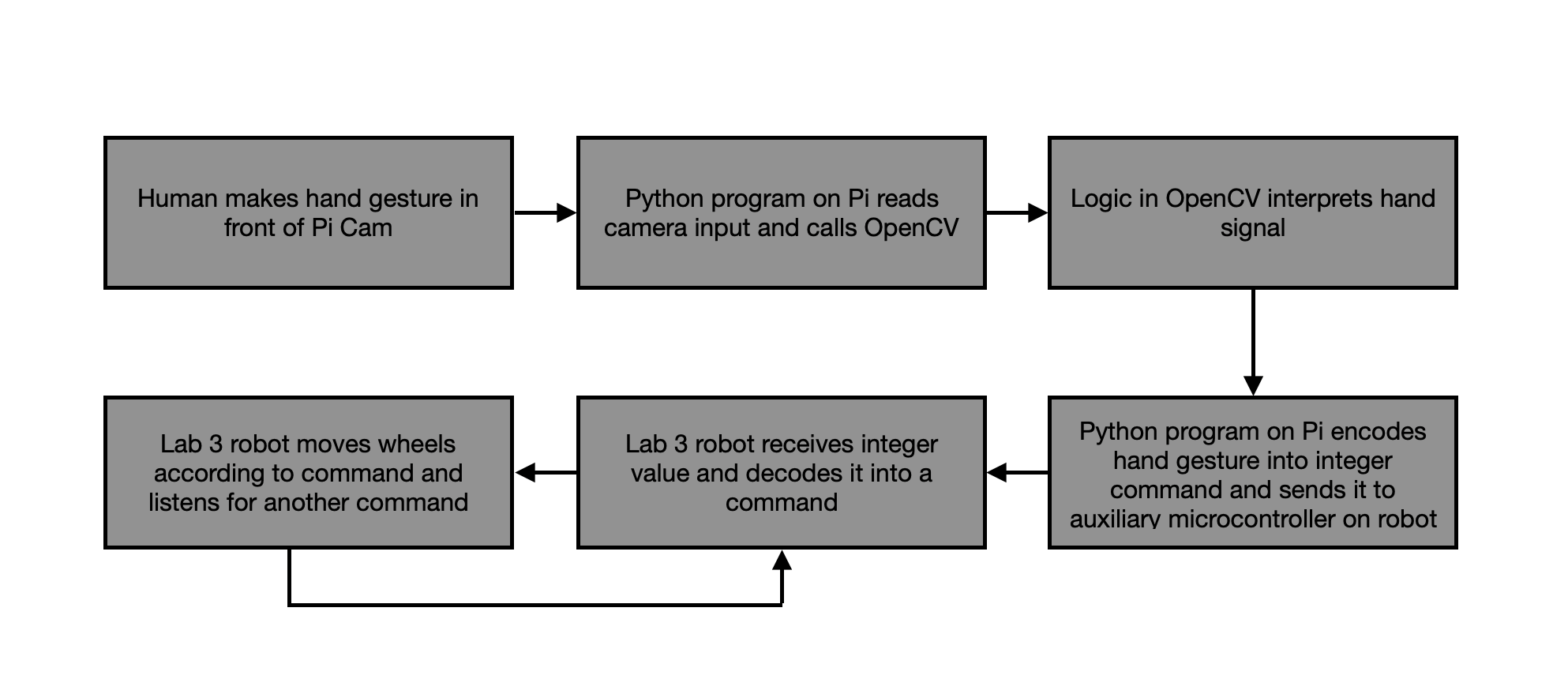
This project used Raspberry Pis in order to synthesize several hardware and software components. The two main elements of the project are each built around a Pi, and are split into the base station and mobile robot. The base station consists of a PiCamera attached to a Raspberry Pi 3. This PiCamera provides a live camera feed, which is filtered and analyzed in order to detect a user’s hand. Once the hand is detected, it is further analyzed to determine what gesture is being made (how many fingers the user is holding up). This information is then sent over bluetooth to the mobile robot.
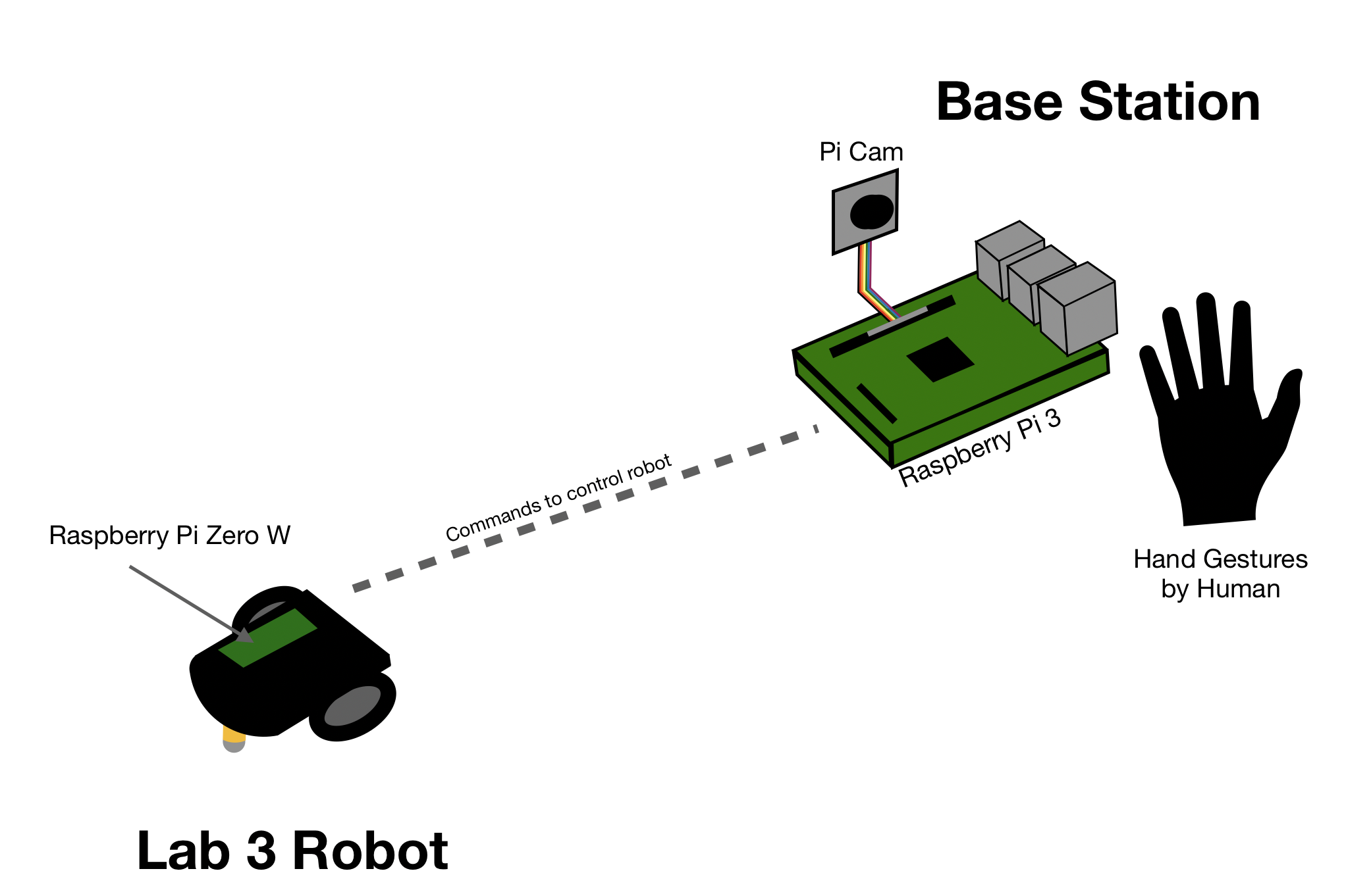
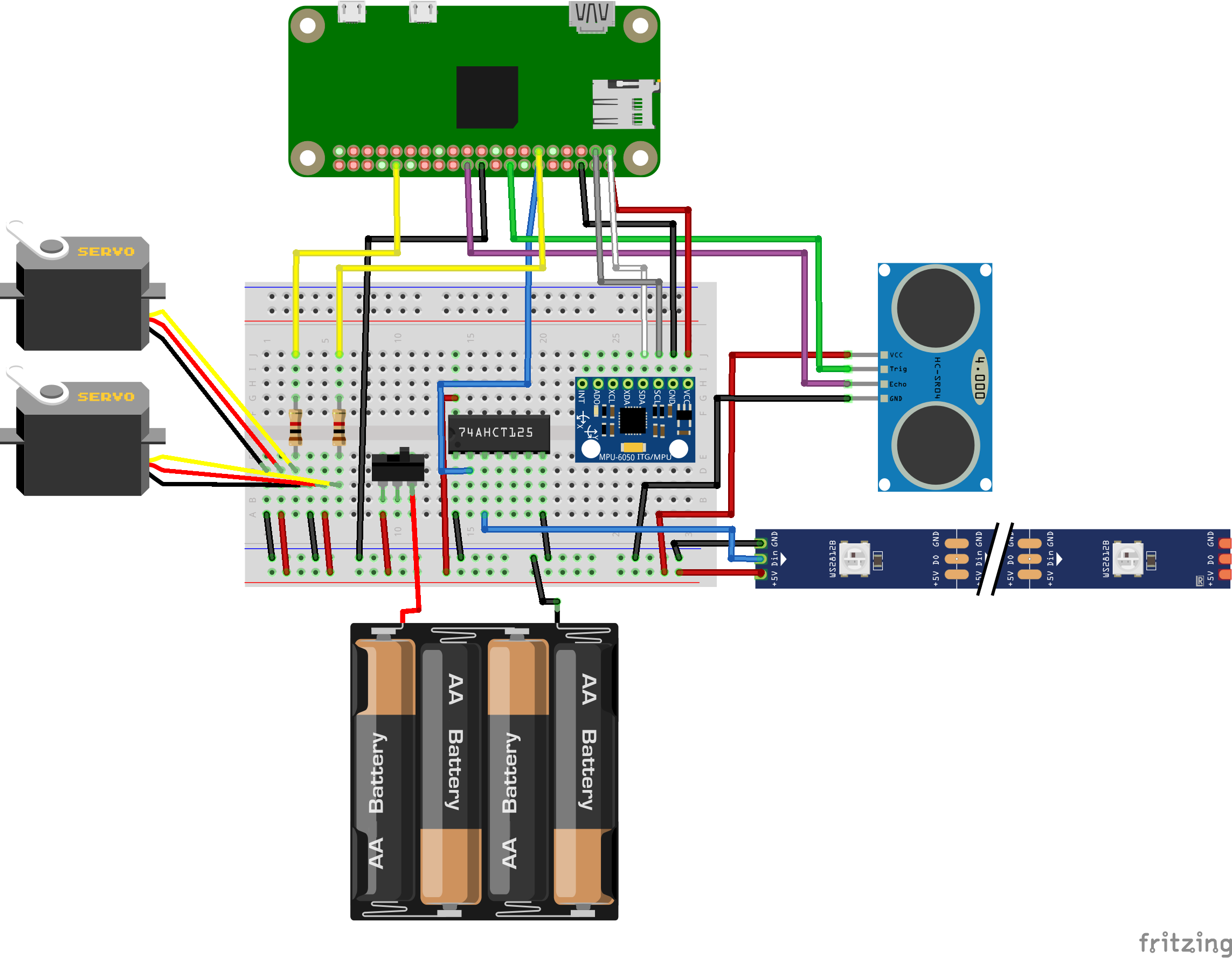
The robot receives information from the base station, and completes the command associated with the gesture being made (forward, backward, left, right, or stop). While executing these commands, the robot uses an accelerometer to correct errors in its straight line motion, and an ultrasonic sensor to prevent collisions with other objects. A diagram of our project setup is shown in Figure 1 below:
Design and Testing
Our design was broken up into 3 parts: hardware design, software design, and mechanical design.
Hardware Design
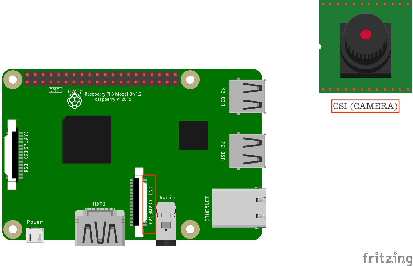
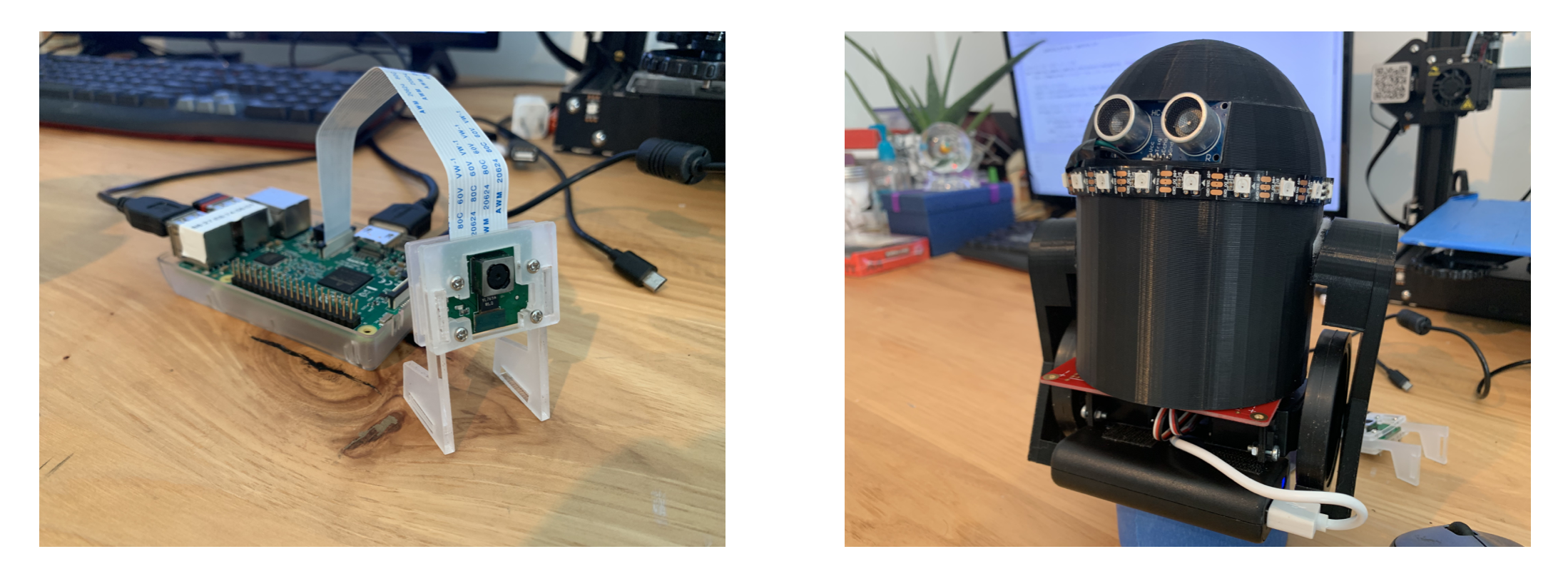
The hardware design involved two parts: the base station, and the robot. For the base station, we used a Raspberry Pi 3, which had a PiCamera wired to its CSI camera port. The Pi 3 also features a BCM43438 Broadcom chip, which provides Bluetooth 4.0, an essential communication protocol in our project.
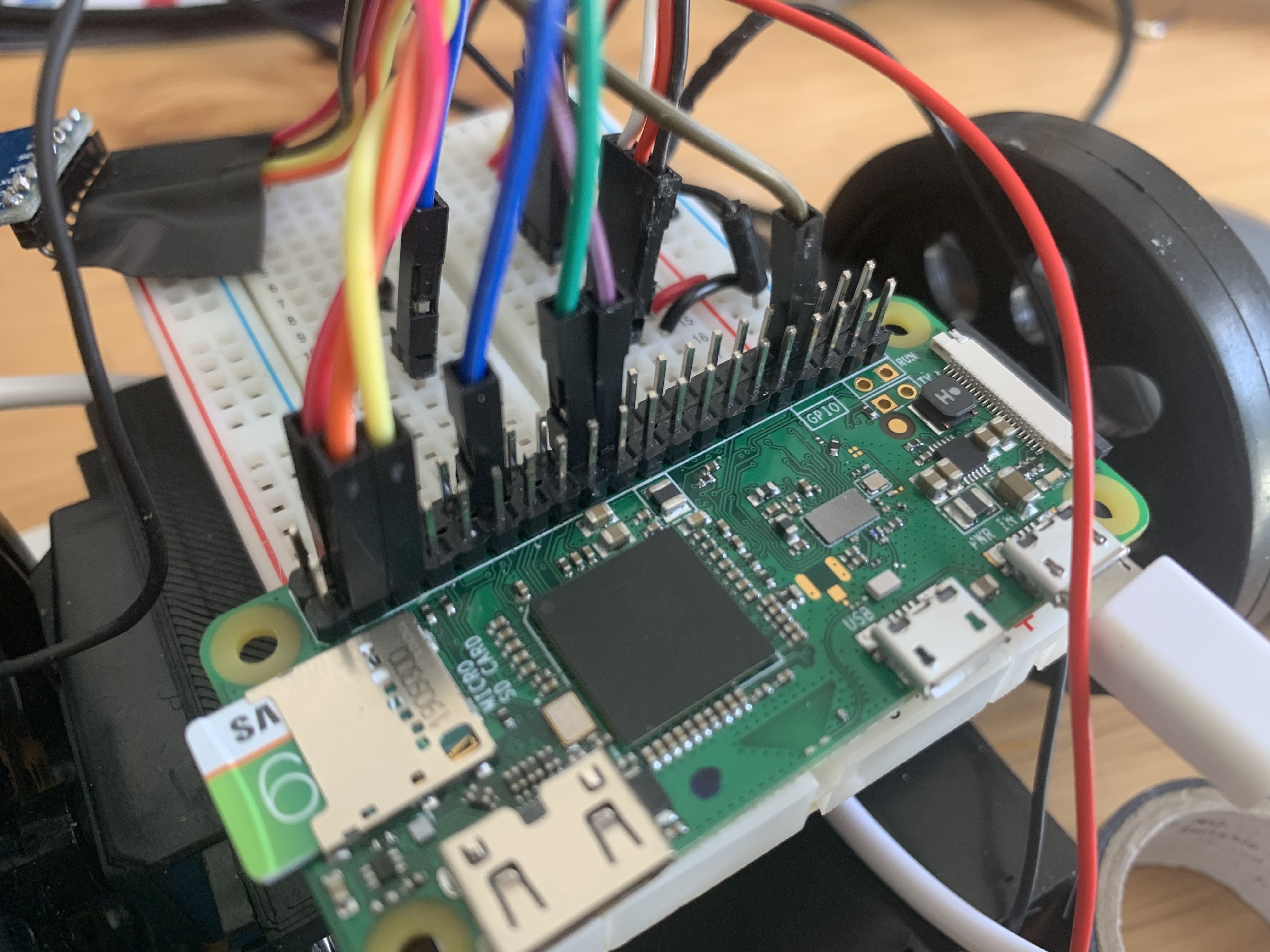
We opted to use the Raspberry Pi Zero W for our robot since it is compact, low cost, and provides enough processing power for our intended tasks. Like the Raspberry Pi 3, the Zero W also features a Bluetooth module, along with the same 40-pin GPIO pin layout.
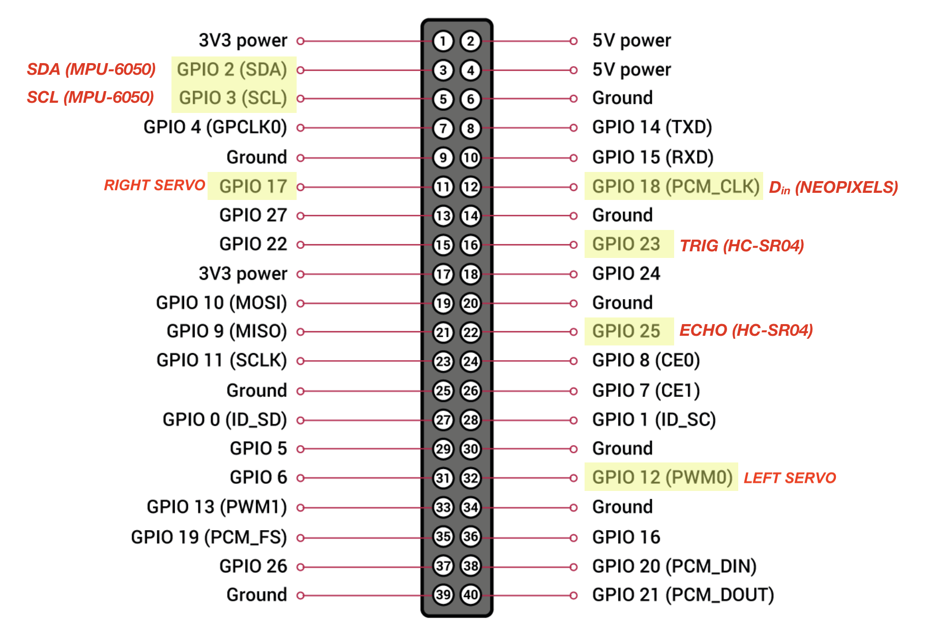
The following image depicts our GPIO pin usage on the Pi Zero W:
Various hardware components that interacted with the Pi Zero W included Parallax servo motors, an MPU-6050 accelerometer, an HC-SR04 ultrasonic range sensor, a WS2812 Neopixel LED strip with a 74AHCT125 quad level-shifter, and a 6-volt battery pack with a slide switch.
Parallax Servos:
We used two Parallax bidirectional, continuous-rotation servos as our motors for our robot. These servos can be communicated to via pulse width modulation (PWM). Each servo’s power and ground lines were wired to respective power and ground lines on a detached 6-volt battery pack, which ensured that they wouldn’t draw too much current from the Pi, and because servos can cause inductive spikes while under load. Signal lines for both servos were wired to a 1kΩ resistor, which were wired to GPIO_12 (left servo) and GPIO_17 (right servo) on the Pi Zero W.
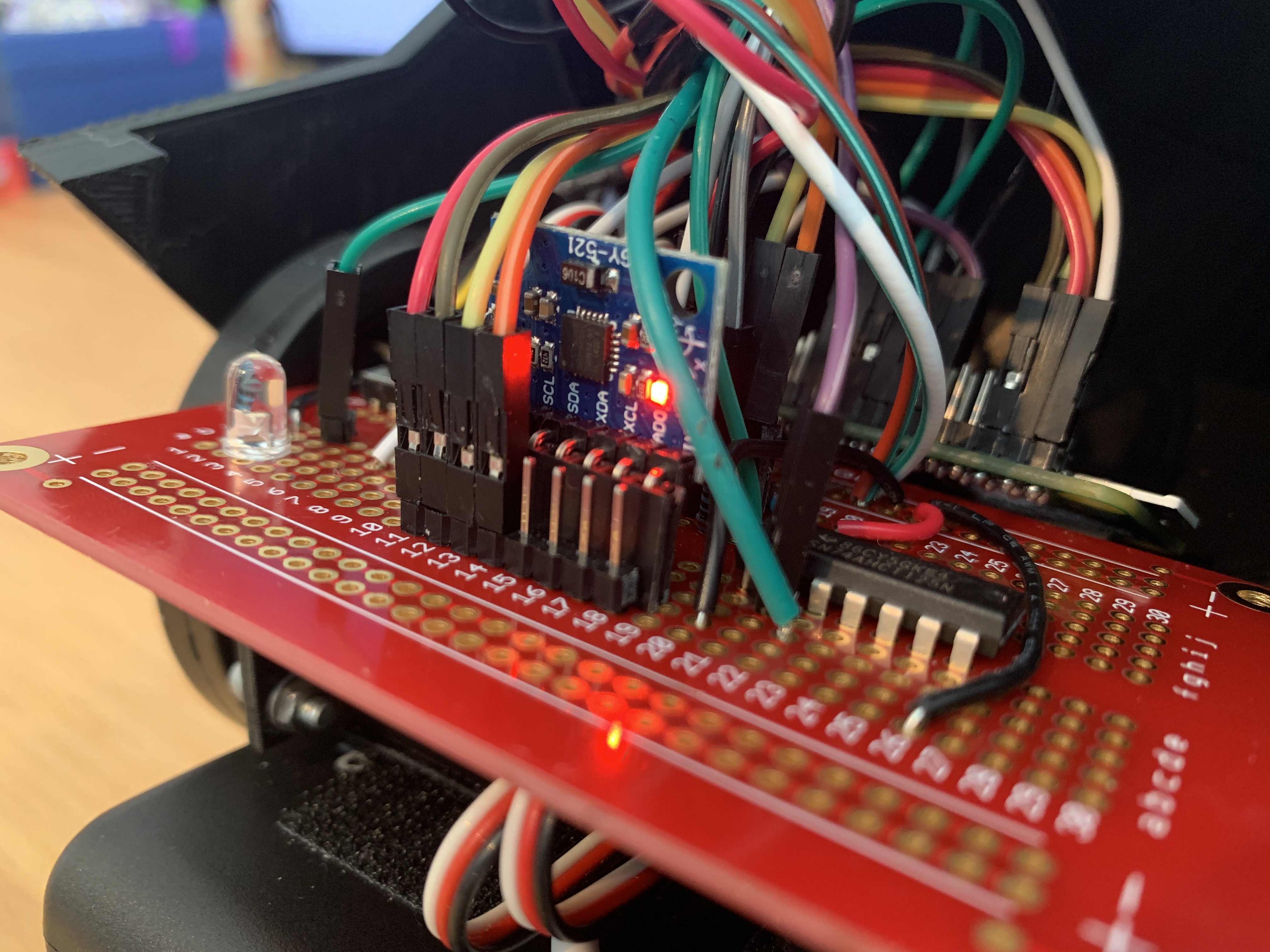
MPU-6050 Accelerometer/Gyroscope:
We used an integrated 3-axis accelerometer and 3-axis gyroscope to correct for off-centered movement while the robot was driving. The power and ground lines of the MPU-6050 were wired to a 5V and ground pin on the Pi respectively, the SCL line was wired to GPIO_2, and the SDA line was wired to GPIO_3 on the Pi Zero W. The SCL and SDA pins are used since the MPU-6050 communicates via I2C.
HC-SR04 Ultrasonic Range Sensor:
We used an ultrasonic range sensor to detect and prevent collisions while the robot was driving. The 5V and ground lines on the sensor were wired to respective power and ground lines on the battery pack. The TRIG line, which is an input pin on the sensor that sends out a “ping” and starts an internal clock in the sensor, was wired to GPIO_23. The ECHO line, which is an output pin on the sensor that indicates that the “ping” has returned and the internal clock should stop, was wired to GPIO_25.
WS2812 LED Strip:
We used a Neopixel LED strip to indicate various states that the robot was in (ie drive mode, panic mode) and communicate which end of the robot was the front. The 5V power line and ground line on the strip was wired to the corresponding power and ground lines on the battery pack since the Pi may not be able to source enough current to light up all of the LEDs.
GPIO pins on the Pi only output 3.3V. The WS2812 datasheet states that the Din line for the LED strip needs 0.7*VDD = 0.7*5 = 3.5V to be driven, so the 3.3V output pins on the Pi needed level conversion. We used a level shifting chip, 74AHCT125, to convert the 3.3V on pin D18 output to about 5V, then wired the Din line to the appropriate pin on the level shifting chip.
Battery Pack and Switch:
We used four AA batteries to supply 6V to the various components described above (when measured with a multimeter, this voltage was ~5.5V in actuality). We used a slide switch so that we could enable powering on/off the components as desired.
Software Design
The software was broken into base station software and robot software. For the base station, software centered around gesture detection. To accomplish this, we first needed to get the PiCamera working. We configured the Pi 3 base station by enabling the camera peripheral. We then ran the command sudo apt get-install python-picamera python3-picamera, in order to get the appropriate python libraries installed in Python 2 and Python 3. At this time, we also installed OpenCV by running a similar command, but replacing the picamera library name with opencv.
Once everything was enabled and installed, we created a Python script to get a live video feed working. In this script, we first defined resolution and framerate parameters to set up the camera using the lines
We then created a variable to gain access to the camera stream with the line rawCapture = PiRGBArray(camera, size=(640,480)). This gave us access to the camera stream in a format compatible with the OpenCV library. We then created a for loop to continuously get frames, and displayed these frames using OpenCV. Each frame had to be caught in a BGR format, in order for the OpenCV library to be able to correctly function. With this set up, we could display the feed from the PiCamera.
Once the feed was working, we focused on analyzing each frame captured in order to detect a hand. For each frame, we conducted preliminary filtering to get a greyscale, smoothed image using the functions
We then needed to determine where the hand was. We decided to do this by asking the user to first completely remove their hand from the camera frame. We then averaged together 20 frames of data in order to get an average background image. The user was then told they could place their hand back in the frame. Each pixel in proceeding frames was compared to our saved background image with the line
If the a pixel was determined to be significantly different from the background using thresholding, it was determined to be in the foreground. The frame was then binarized so the foreground was white and background was black.
We got the idea to average the background because of initial difficulties we faced while trying to detect hands. Initially, we thought to look for the hand in certain defined regions of the screen. However, this seemed to limit the user to get their hand to fill a small box that we defined. Because we wanted the user to be able to comfortably place their hand anywhere in the frame, we then began to consider detecting the hand based on skin color. In this iteration, we would ask users to place their hand in a certain part of the frame only so that we could calibrate to their skin tone, and then they would be free to place their hand anywhere. However, this proved to be difficult to accomplish given varying lighting conditions even within the same trial; the user simply moving their hand away from the camera could sometimes cause an unrecoverable shift in the pixel color of their hand. We therefore arrived at the idea to average background frames. This allowed the user to place their hand anywhere, using any natural background and any camera angle. If, at any point during the trial, the user’s background changed and gesture detection no longer worked, they could optionally re-average the background by clicking “a” on their keyboard.
We then looked for contours in the binarized image. To reduce noise, we focused on only the largest contour, and assumed the largest object different from the background was the user’s hand. We then looked for contour defects with the following code:
These lines first calculated a kind of best-fit polygon for the largest contour. Then, the convex hull of this approximate polygon was found, meaning that a polygon was found that did not have any points which bend inwards. Finally, defects were found by comparing the best-fit polygon with the convex hull. The best-fit polygons had inward bends for the gaps between the fingers, but the convex hull did not. Therefore, the number defects found generally correlated with the number of fingers the user was holding up. Gesture information was sent over bluetooth to the mobile robot.
Bluetooth communication between the base station and robot was established using the PyBluez library. Once we installed PyBluez on both the Pi 3 (base station) and Pi Zero W (robot), we enabled Bluetooth on both and attempted to connect via the command line. Once the Pis were connected, we worked on communication between them using Python. To do this, we set up the base station as a client and the robot as a server using an RFCOMM bluetooth socket. The server socket was set up, bound to its local bluetooth adapter, and told to listen to a specific port using the lines
The server then attempted to accept a connection using the line in a try block:
This allowed the server to wait and accept a connection once the client was ready to connect. The client was set up to connect to the server’s MAC address and send messages to the specific port the server was listening to with the lines
Once the base station and robot were connected, the base station sent a code for the detected gesture for every frame that the PiCamera collected data using the command:
The server received the data in a while(1) loop within the try block using the line
Once the connection was severed, all sockets were closed.
Upon a successful bluetooth connection with the base station, the Python script running on the robot had a main loop where the commands that were received were decoded. These possible commands were UTF-8 types, and converted to Strings using data.decode(‘utf-8’). The six valid possible commands that were received from the server were as follows:
- "0" - Quit program
- "1" - Move forwards indefinitely
- "2" - Move backwards indefinitely
- "3" - Pivot left for a finite duration
- "4" - Pivot right for a finite duration
- "5" - Stop all movement
The robot’s software checks if the incoming command is one of the six listed above. Then, it calls the function valid_command(), which checks if the last six received data points from the base station all match, ensuring that the data point received (based off of the user’s hand gesture) was actually the intended command. The function valid_command() uses an array called command_arr to store the previous six commands.
The software also checks that the command to be executed is not the same as the previous command executed. This prevents execute_robot_command(s) from being called an unnecessary number of times (and prevents the software from overwriting the same PWM signal too often).
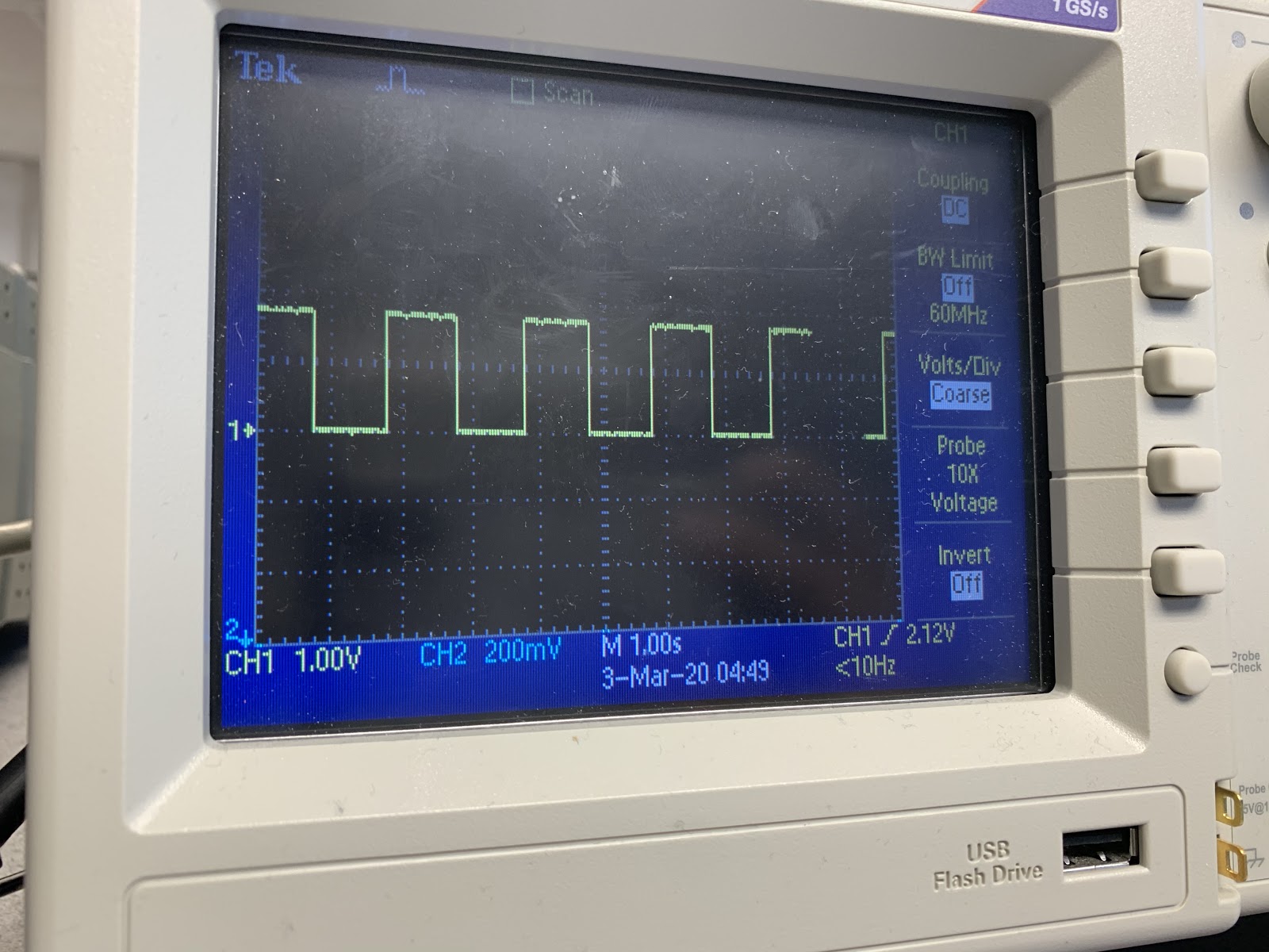
The various commands were carried out by writing a PWM signal to each of the GPIO pins that the motors were connected to. PWM signals have multiple parameters that dictate the nature of the signal, and the nature of the signal dictates how a servo should respond to it. Typically, PWM signals have periods slightly longer than 20 milliseconds (ms). Within this period, the signal stays mostly low except for one instance of a square pulse. The length of the square pulse varies based on whether the servo is meant to move clockwise, counterclockwise, or stop.
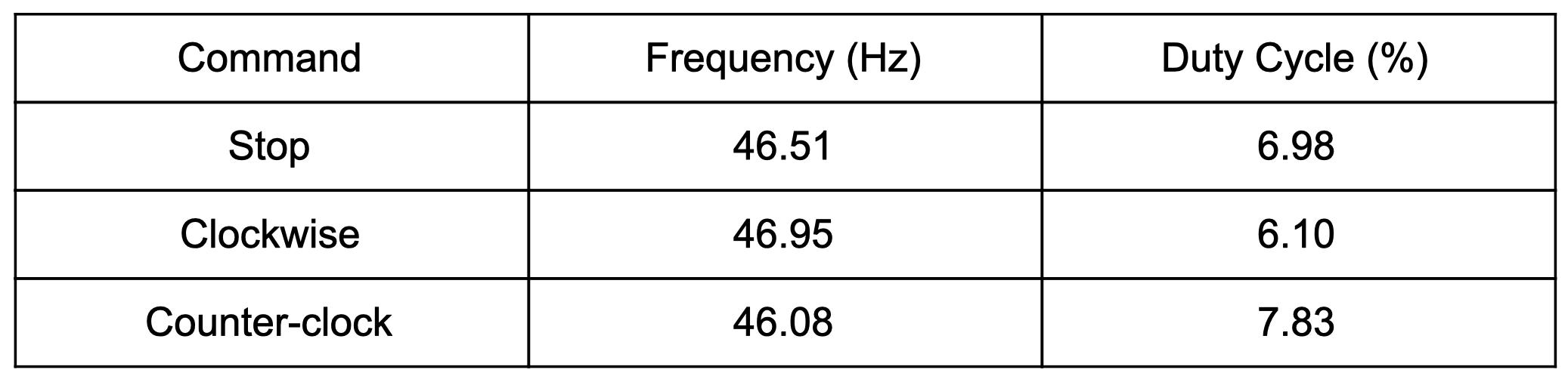
Using this equation, we calculated the duty cycle for the full speed clockwise signal was 6.10%; for stop it was 6.98%; and for full speed counterclockwise it was 7.83%. We used these duty cycle and frequency values to change the direction that the left and right wheels were turning on our robot.
For the Parallax servos we used, a pulse of 1.3 ms meant full speed clockwise, 1.5 ms meant stop, and 1.7 ms meant full speed counterclockwise. These pulse lengths add on to the base period of 20ms, so the period for full speed clockwise was 21.3ms, for stop was 21.5ms, and for full speed counter clockwise was 21.7ms. The frequency of a signal is defined as one over the period, so the frequency of these signals were 46.95Hz, 46.51Hz, and 46.08Hz respectively. Another parameter used to define PWM signals is duty cycle, which is defined as the percentage of time the pulse is high within the period of the signal as a whole. In equation form:

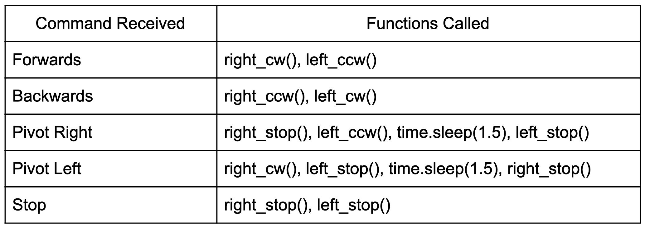
We wrote the functions left_cw() (left wheel clockwise), left_ccw() (left wheel counterclockwise), left_stop() (left wheel stop), right_cw() (right wheel clockwise), right_ccw() (right wheel counterclockwise), and right_stop() (right wheel stop), which called the PWM library's ChangeFrequency(f) and ChangeDutyCycle(dc) to enact directional changes to the left/right servo when called.
We called the functions described above based off of the command that was received over bluetooth in a function called execute_robot_command(s). The execution of this function is described in Table 2.
To accomplish wheel movements, we used software PWM. Unlike hardware PWM, software PWM does not always have “rock solid pulses” and the stability depends on system activity. This posed some challenges for straight-line robot movement, which highly depends on a reliable PWM signal. While one option to ensure straight-line movement was to use the pigpio library to implement hardware PWM, we kept our software PWM implementation and instead used an accelerometer/gyroscope module to detect off-centered robot movements.
To use the MPU-6050 accelerometer, we first enabled I2C on the Pi Zero W since this is what the module is compatible with for communication. In our Python software on the robot, we initialized and wrote to various MPU-6050 registers. Then, the function read_raw_data() read the 16-bit values of the accelerometer and gyroscope. This function was called in our main loop if the robot was moving forwards:
Here, we read the gyroscope on the y axis, then check if the absolute value of the reading is greater than four degrees per second. We define this movement of greater than 4 degrees per second as the robot moving off-center and requiring direction correction. Based on the incorrect way the robot moves, we correct it by calling either piv_left_corr() or piv_right_corr(), which briefly (0.1 seconds) stops one wheel to allow the robot to return to center.
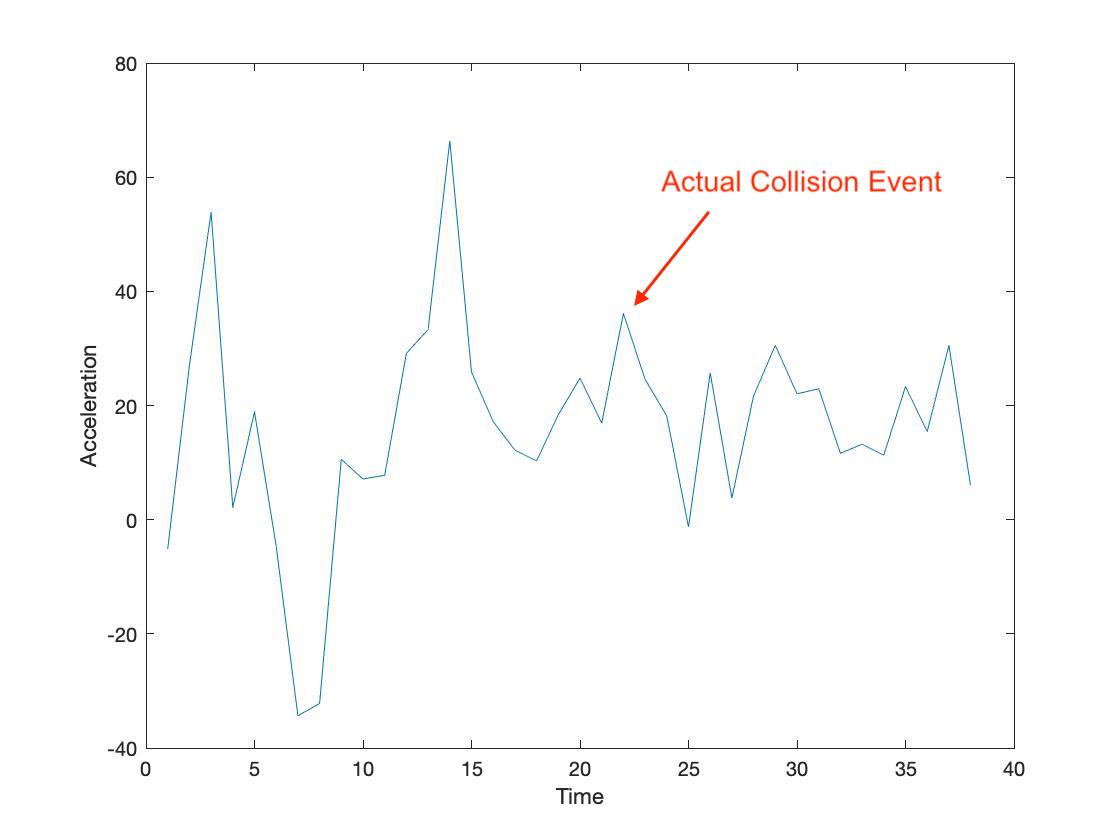
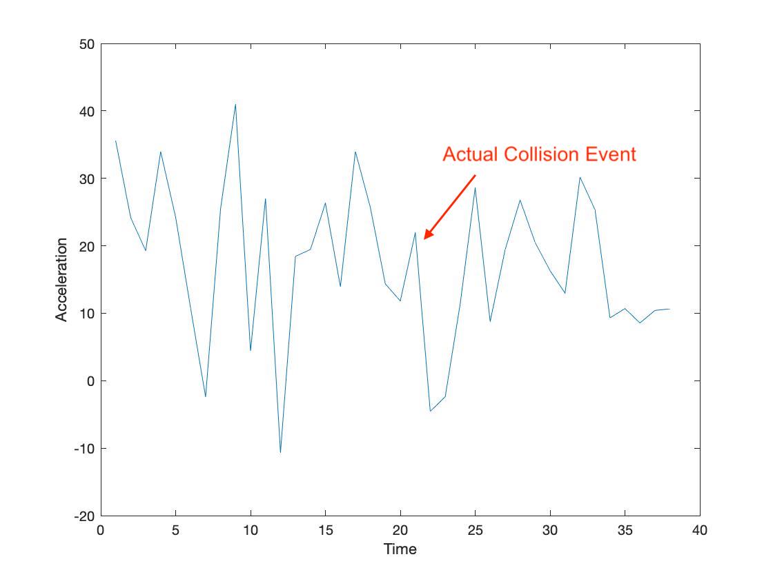
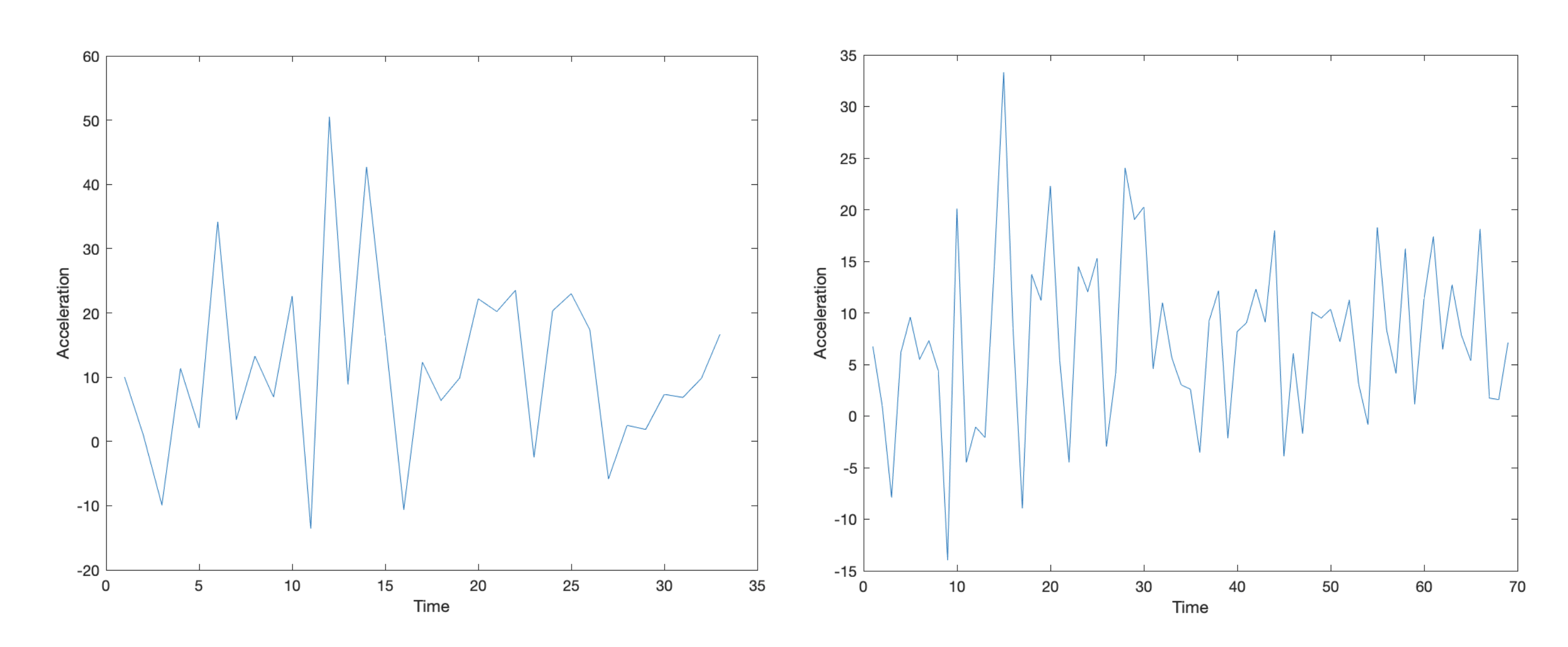
While we had initially planned to also use the y-axis acceleration profile of the accelerometer to detect collisions and stop the robot from moving, we noticed that the speed of the robot was not fast enough to provide a distinct acceleration profile for collisions over regular robot movements (see testing section).
Because having reliable collision detection was a key aspect of our project, we instead used an ultrasonic range sensor to avoid collisions all together. Our function distance() was called on every iteration of the main loop.
In the distance() function, a logical high, followed by a logical low signal, is sent to the TRIG pin on the range sensor. Then, a timer is started.
This sets tells the sensor to send out a “ping” and times how long it takes to return. When the “ping” has returned, the ECHO pin on the sensor is set to logical high, which tells the timer to stop. Then, we calculated the distance based off of the time that has elapsed and returned distance.
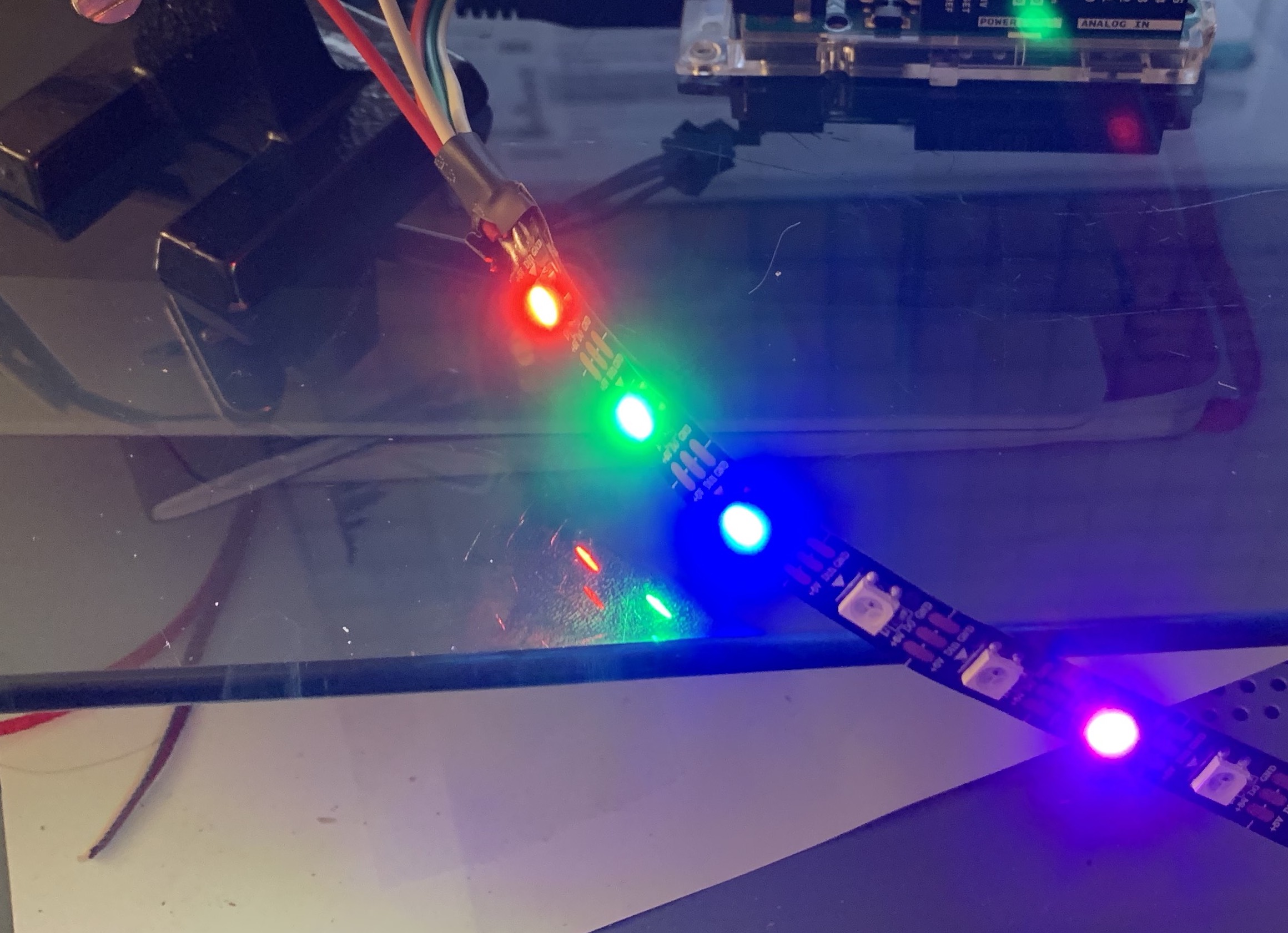
We used distance() to detect potential collisions by comparing the value returned to a preset threshold (30 cm). If the distance returned by distance() was smaller than this threshold, the robot initiated a “panic stop,” in which the robot stopped for one second, (execute_robot_command("5")), then moved backwards for one second (execute_robot_command("2")), then stopped again until the next command was received. In addition to executing this sequence of commands, we programmed the neopixel LED strip to illuminate in all red while in “panic stop” mode, so that the driver could have a clear indication that the robot was autonomously moving to prevent a collision.
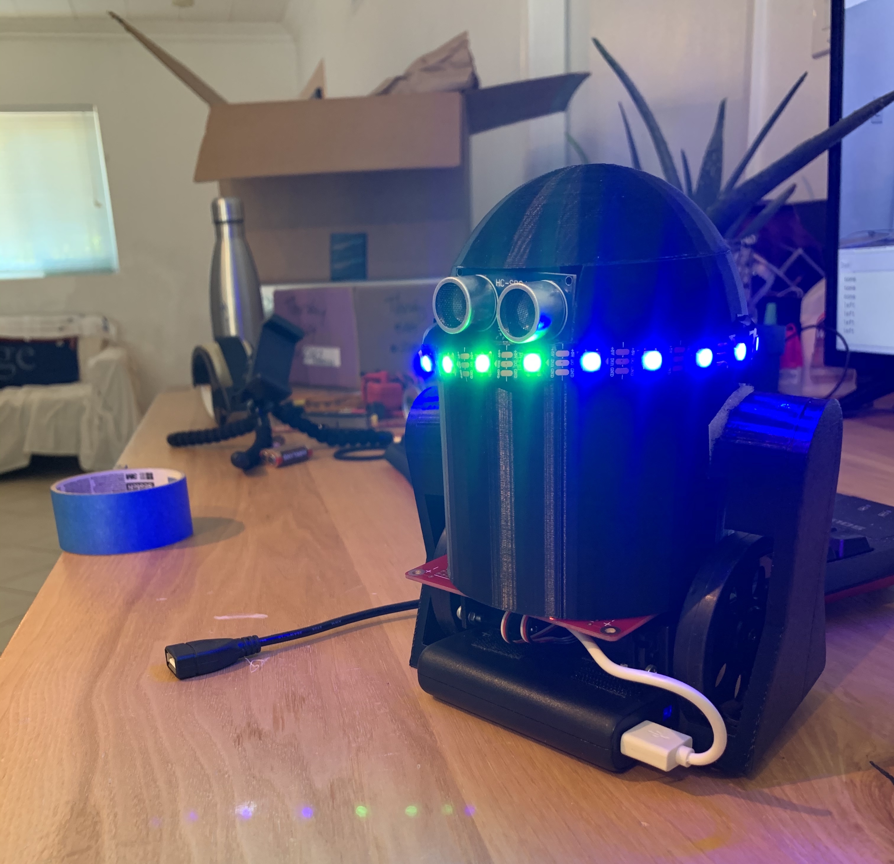
When the robot is driven by the user based off of hand signal-control, the neopixel LED strip illuminates in green light on the front of the robot, and blue light around it. The green lights allow the driver to easily identify the front of the robot.
In the robot’s software, an array of size 20 called pixels was initialized by indicating that the data line of the neopixel strip (the output of the 5V level-shifter in actuality) was wired to GPIO_18, and that there were 20 neopixels in total.
Before the robot’s software had initiated a successful bluetooth connection with the base station, we illuminated the neopixel strip in teal by using pixels.fill((0,255,255)) to indicate this mode. During “panic stop” mode, we used pixels.fill((255,0,0)) to illuminate all 20 neopixels in red. During regular hand gesture-controlled drive mode, we illuminated all neopixels in blue, and three neopixels on the front in green.
Mechanical Design
We designed our robot’s frame, body, and fitting of electronic components.
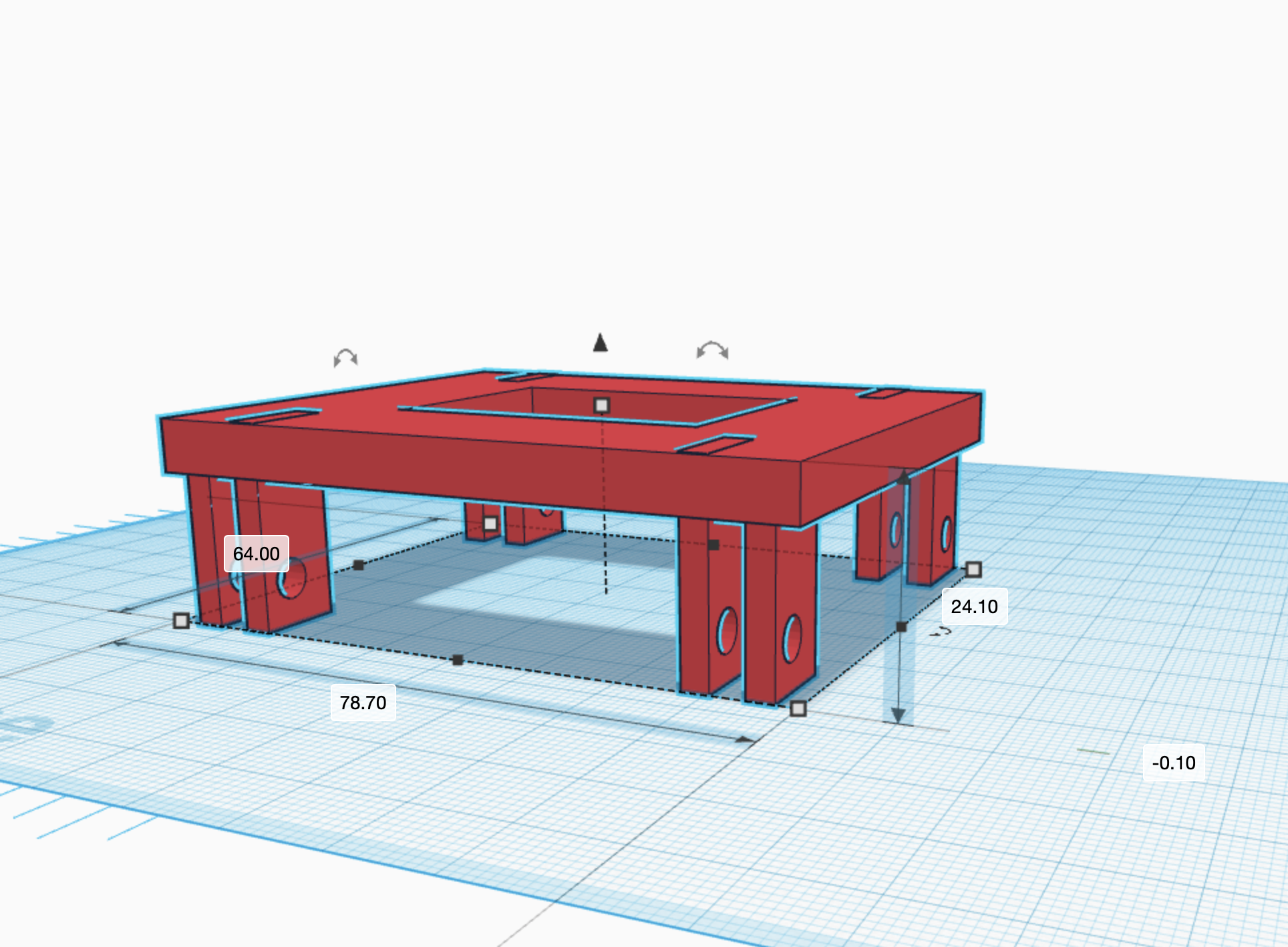
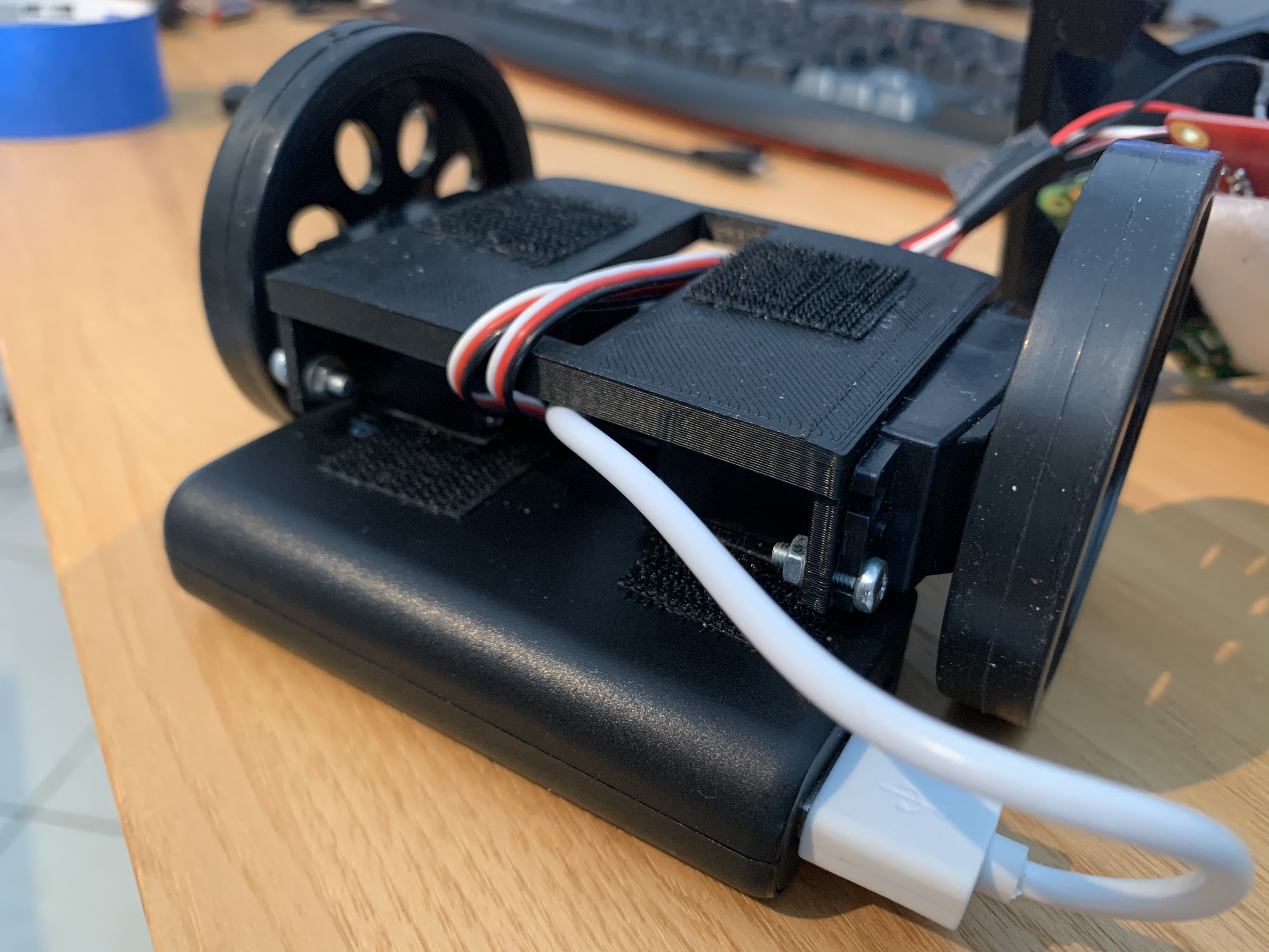
The frame consisted of a single 3D printed piece shown in figure 8. It has M1 holes for mounting both servo motors at the end of the frame. It is lifted (~24mm) to provide space for the battery pack and battery holder to sit underneath it. The frame also features a square hole for room to route wires from the batteries and servos. The frame was 3D printed using PLA material.
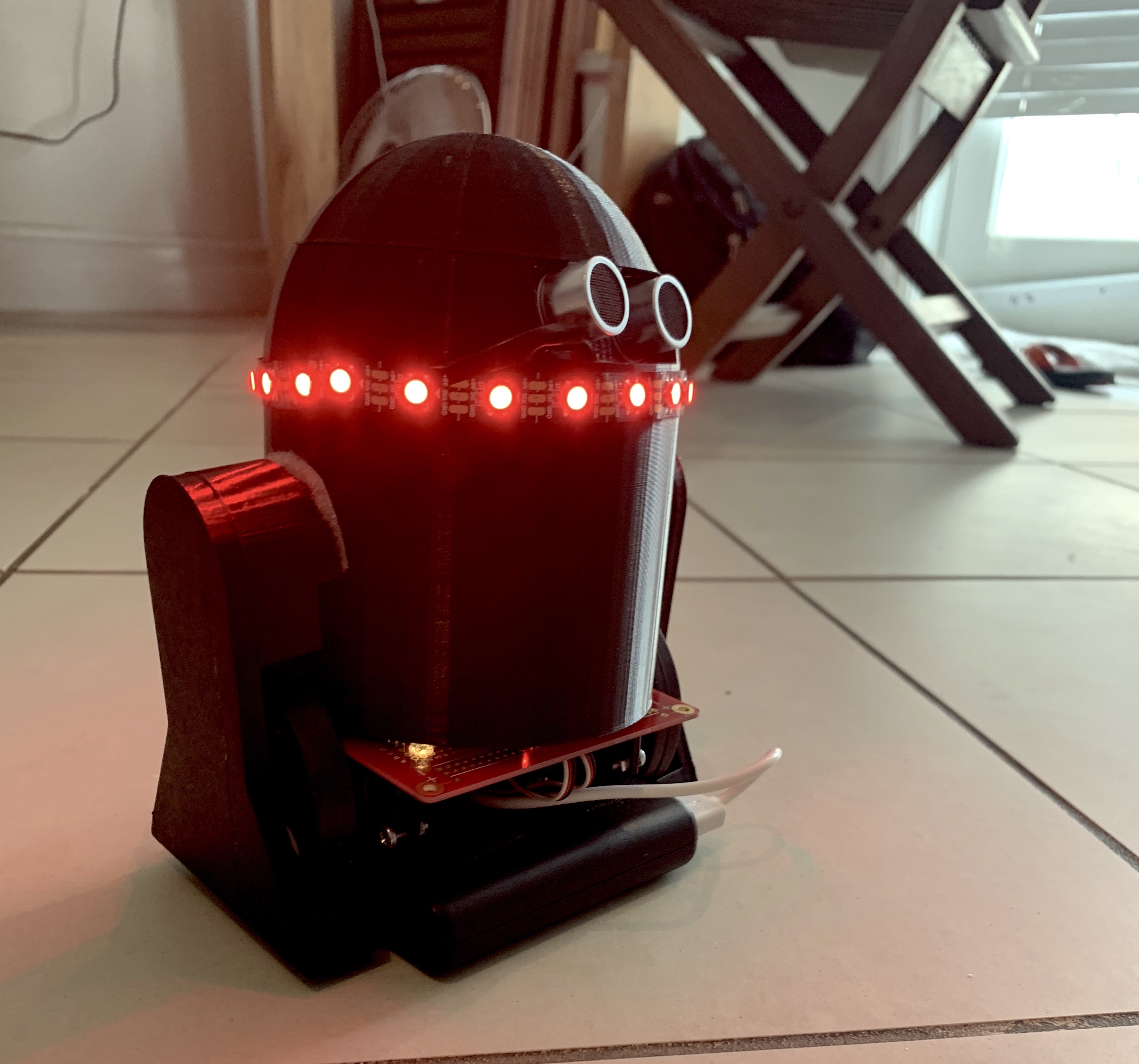
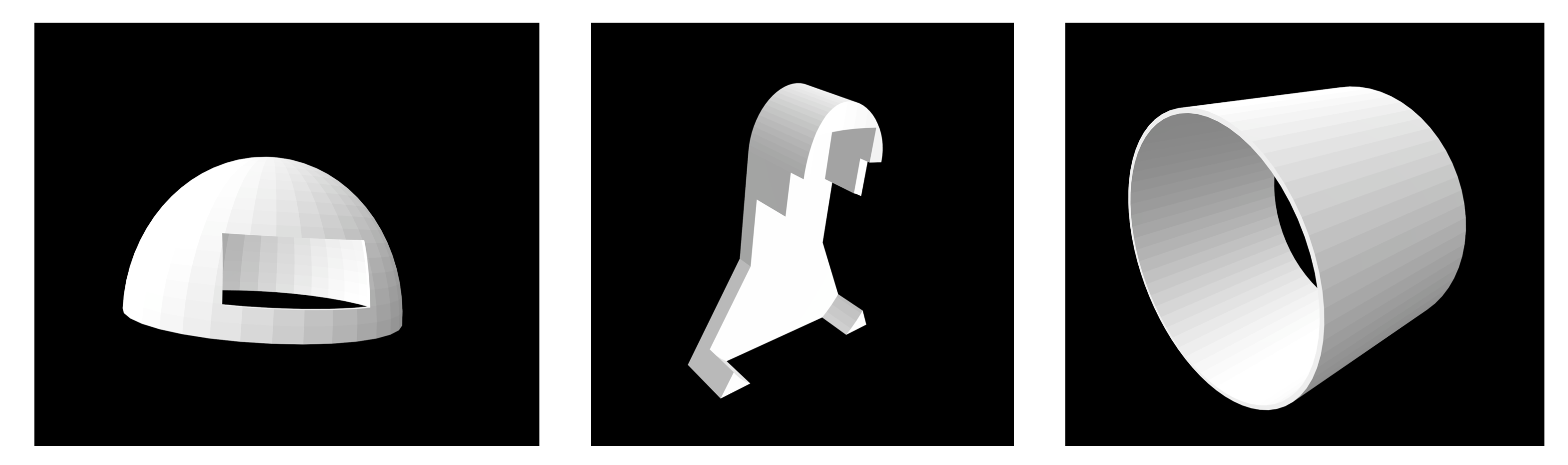
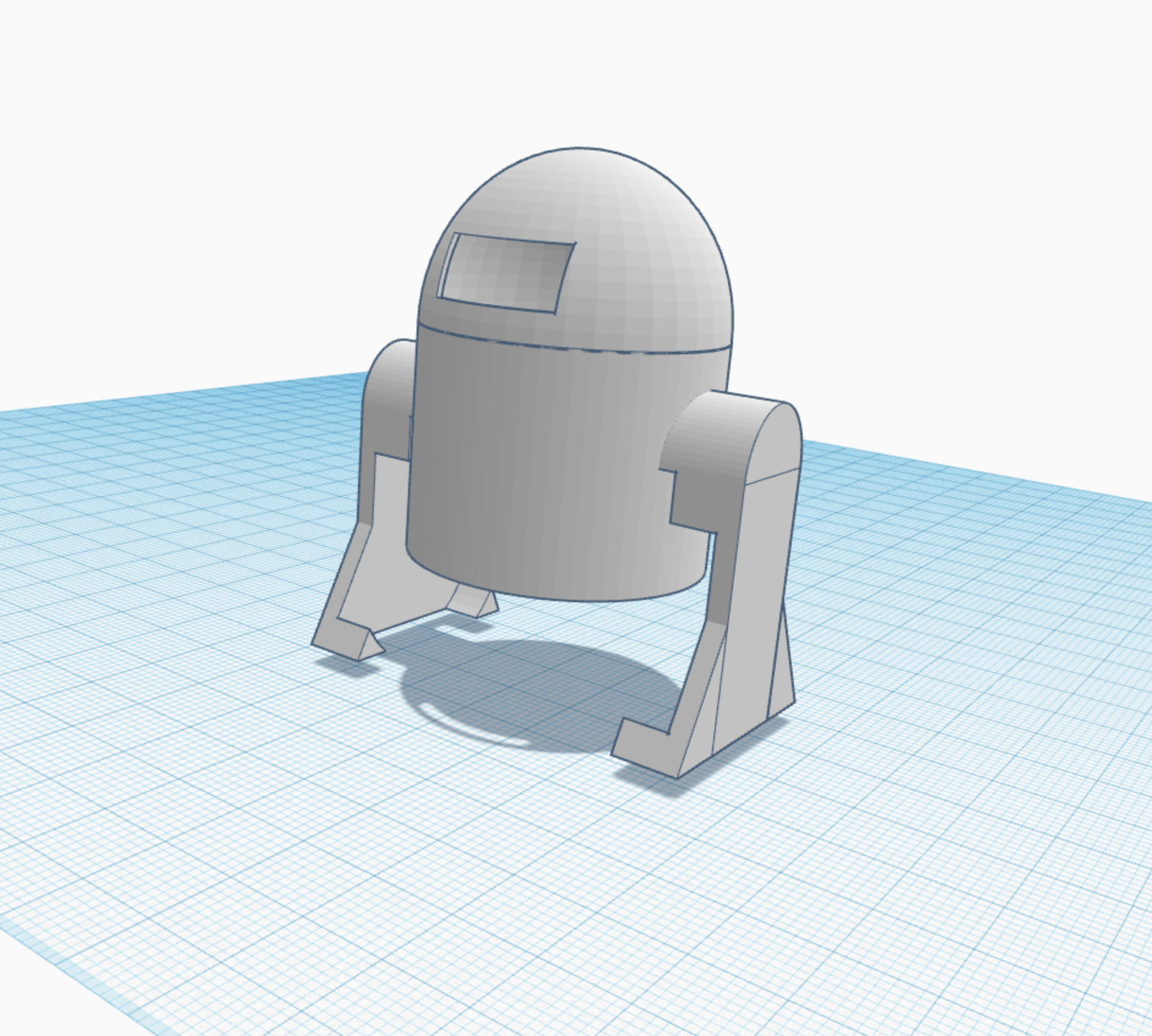
The body of the robot was inspired by the Star Wars character, R2D2. Its purpose however, is primarily to provide a mounting place for the HC-SR04 ultrasonic range sensor and keep wiring from tangling. It features three separate 3D printed parts: “legs” that house the wheels, a "head" that has a mounting spot for the ultrasonic sensor, and a “body” that houses the rest of the robot.
Testing
All of the hardware components were tested for functionality individually on a solderless breadboard to ensure that if their wiring needed to be changed, it would be fairly easy to do so. Header pins were soldered to the Pi Zero W instead of wires directly soldered to the Pi to ensure that wires could be removed/added easily.
Software testing began with making sure the PiCamera worked properly. To iteratively test, we first made sure the camera could take single frame photos. Once we could see the correct photos saved in a JPEG format, we learned how to capture and display frames with OpenCV. We chose to get a live video feed running in this manner because we knew that we would later use OpenCV to perform gesture detection. We got the video feed working without facing any major issues.
We then tested hand detection. To do this, we first drew the contour that was supposed to represent the hand onto a black display. We then additionally drew the polygon and convex hull. When each of these elements worked, we found the defects, and drew those to the screen as well. An image of the drawing including detects and the convex hull approximation is shown in figure 12 below:
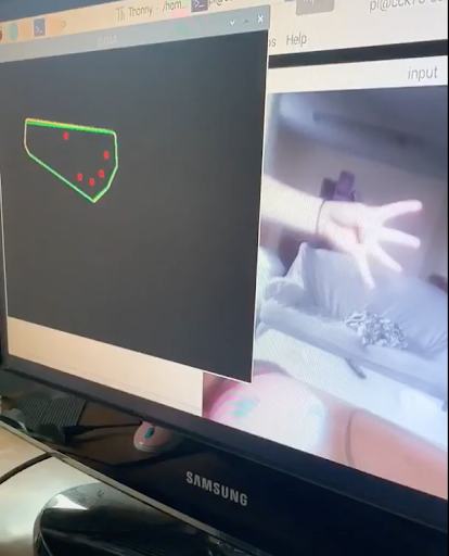
Once the defects worked, we used them to see if we could reliably differentiate gestures. We did this by using our script in many different lightings with multiple backgrounds and camera angles. Though some setups worked better than others, we found that we could fairly consistently tell how many fingers a user was holding up, regardless of their environment. We therefore determined that gesture control was working.
After getting gesture detection working, we moved on to test bluetooth. While we progressed smoothly through connecting the Pis using the command line, we initially struggled to implement a connection using Python. After further research, we realized our issues stemmed from running our scripts in the incorrect order. If the base station script was started first, the robot would not yet be listening for a connection. Therefore, the base station would get an error stating the connection was refused, and the robot would listen forever for a connection that it could never make, given that the base station had already tried and failed to connect. Once we made sure to start the robot script before the base station script, our bluetooth worked as expected, and could reliably send messages as long as we left both scripts running.
We tested our robot’s software by testing writing seperate programs to test each of the components. For example, to test functionality of the servos, we used a Python script called “two_wheel_test.py,” where a user could input a desired command (forwards, backwards, pivot right, pivot left, stop), to test if the servos would drive correspondingly.
Another separate program we wrote was “ultrasonic_test.py,” which tested the functionality of the ultrasonic range sensor. This standalone script consisted of the distance() function (described earlier), and had a main loop that called distance() every 0.2 seconds, and displayed the measured distance in the console window. To test this program, we placed our hands at various distances from the sensor to see if the output changed as we expected.
To test the accelerometer/gyroscope module, we wrote a separate script called “accelerometer_test.py,” which initialized and wrote to various MPU-6050 registers. Our main loop of the program read accelerometer and gyroscope data from the x, y, and z axes and displayed the output in the console window every 0.5 seconds. We tested functionality of the MPU-6050 by moving it on a single axis, then reading the value on that axis to see if it changed correspondingly.
We tested the accelerometer as a device for straight-line correction by mounting it on the robot and driving the robot forwards. Then, we displayed the gyroscope profile of the y-axis (the y axis was measured because of the orientation of how we mounted the accelerometer on the robot) to the console window, and observed changes in this value when the robot veered in one direction more than the other. As described in the previous section, we noticed that this threshold value was 4 degrees per second. Then, based on this threshold, we corrected the movement by stopping one of the wheels for 0.1 seconds.
Since our original plan was to additionally use the accelerometer to test for collisions, we allowed our robot to make multiple runs and intentionally crash into walls or other objects. During these crash events, we recorded y-axis acceleration data every 0.2 seconds. After each run, we took these datapoints and plotted them against time in MATLAB, as we expected to see a large drop in the acceleration during the crash event. However, after graphically viewing these profiles, we could not see a consistent acceleration pattern that indicated a crash, relative to all the other data points, so we decided not to use the accelerometer as determination for a collision, and relied on the ultrasonic range sensor instead. We believe that this was likely due to the fact that the robot was not moving at a fast enough speed to clearly create a great enough acceleration (deceleration) during a crash.
The last hardware component that we individually tested was the neopixel LED strip. The standalone script we wrote to test it was called “pixel_test.py,” where we lit up individual and all neopixels during different iterations, to ensure that based on how we programmed the strip to light up, it responded with the intended output. As discussed in the previous section, we added a 74AHCT125 level-shifter to up the 3V output voltage on the GPIO pin to 5V. Prior to adding the level-shifter, we observed strange behavior on the output of the LED strip (incorrect neopixels illuminating, incorrect colors).
Once we tested each component on the robot separately, we individually integrated the multiple software components into one script called “robot.py.” The script first featured command-based control of the robot via bluetooth from the server. This featured functions from our test script, “two_wheel_test.py.”
When the robot could successfully be controlled by commands given over bluetooth, we integrated the accelerometer code from “accelerometer_test.py” with “robot.py.” We continued to test that the robot could still receive commands and execute accordingly with the new accelerometer code integrated, and tested the robot to ensure that it would direction-correct in parallel.
Then, we integrated code from “ultrasonic_test.py” with “robot.py,” tested functionality of how the robot drove, and tested to make sure that the accelerometer could detect collisions in parallel with the other tasks we had programmed the robot to do.
We lastly integrated code from “pixel_test.py” with “robot.py.” When we did this however, we received error messages that the GPIO pin we chose to use was invalid with the board/neopixel library. While we are not sure why most GPIO pins are incompatible with use of this library, we found that GPIO_18 was compatible. Since originally, GPIO_18 was the PWM signal to our right servo motor, we had to designate another GPIO pin (GPIO_17) as our right servo motor.
Once we tested total integration of hardware and software components on the robot, we tested the system as a whole by building a cardboard “playpen” for the robot to drive around in. We simultaneously ran the robot and base station, and controlled the robot based on holding up a different number of fingers in front of the camera. The playpen allowed the robot to have the opportunity to execute its “panic stop” mode, since it was eventually bound to interact with a wall.
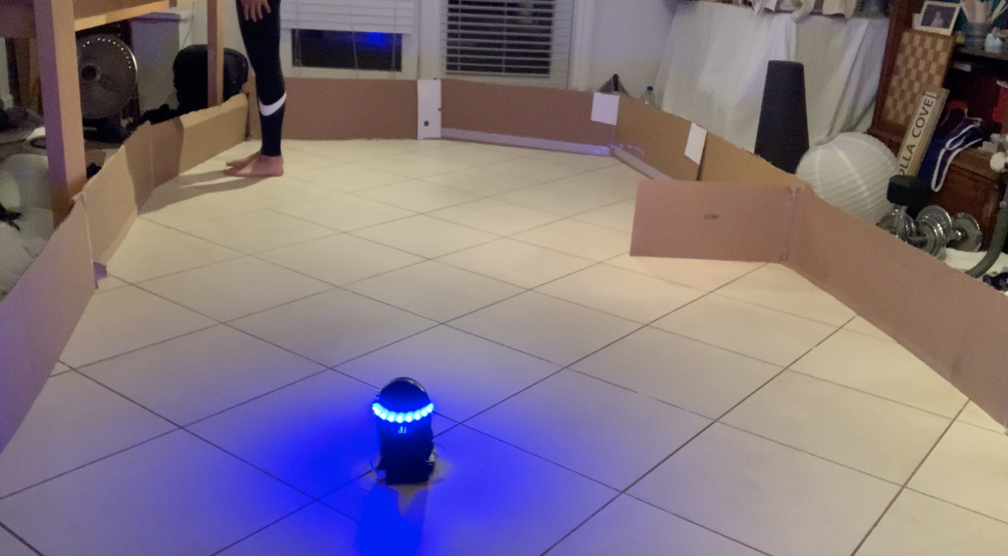
After testing each command (forwards, backwards, pivot left, pivot right) based on the number of fingers we held up in front of the camera and observing the robot behave as we expected, observing straight-line correction when necessary, and ensuring that when the robot detected a potential collision it entered “panic stop” mode, we were certain that our final system worked as a whole and as we intended.
Results
Our final system worked as planned. We were able to detect gestures against nearly any background, and consistently send this data over bluetooth to a robot. Though we occasionally needed to adjust the angle of our hand to get a better reading, we believe that our system still works better than expected due to the versatility of environments it can function in.
Our robot also worked as outlined in our goals. We successfully built a mobile system which could quickly respond to commands it received over a stable bluetooth connection. It was also able to generally travel along a straight line using accelerometer data, and prevent collisions using ultrasonic sensor data. Though we ultimately used an ultrasonic sensor to prevent collisions rather than an accelerometer as we intended, we did meet our goal of implementing emergency stop functionality in case of collision. An accelerometer for detecting collisions ultimately proved to be too difficult to robustly implement given the slow speed of our robot, and it proved to be dangerous to our system in that we had to allow the robot to actually collide with something in order to detect a collision. The ultrasonic sensor allowed us to detect collisions before they occured, and safely stop the robot before causing damage.
Overall, though we needed to slightly adapt our implementation from our original plan, we did meet all of our initial goals. We also added extra functionality to increase usability including LED strips on the robot, and the option to re-average the background if the user’s environment changed. A video demonstration of our project is shown below:
Conclusion
We achieved working gesture detection and bluetooth communication, and constructed a robot which could successfully correct deviations in its straight line motion using an accelerometer and prevent collisions using an ultrasonic sensor. Throughout this project, we have found that it is quite challenging to consistently calibrate cameras to users’ environments. We therefore decided to calibrate each time our system was used by including background averaging. We also decided to give the user the option to recalibrate to their background in case they were to experience some change in lighting or background object placement during use. We have also found that constructing a mobile robot without any sort of line correcting behavior leads to fairly undefined behavior. We therefore learned that we needed to line correct even when the robot was being directly controlled by a human, in order to remove some of the burden on the user and to ensure that, when instructed to go forward, the robot goes forward in a straight manner.
We believe we have created something both entertaining and practically valuable. While unique remotely controlled devices can provide a sense of novelty and amusement, they are also invaluable in that they are able to go places not typically accessible by humans, or assist humans who are otherwise confined to one area. Gesture control is an intuitive, interesting, and easily expandable way to control these useful remote mobile robots.
Future Work
If we had more time to work on the project, we believe it would be very interesting to try to expand our gesture control algorithm. While this might require the use of neural networks, we may have been able to more primitively expand gestures by employing a varying number of fingers on the second hand. If we were to use a neural network, we would have also liked to add functionality so that the user could choose to indicate whether the detected gesture was correct or incorrect. This way, our network would be able to continuously improve.
We also would have expanded our use of the ultrasonic sensor. It may have been interesting to send collision data back to the base station, so that the user could use the data to correct the gestures they chose to send. This could be useful if the robot ever goes out of sight. On this note, other additional data could be sent back to the user. It would be interesting to add a camera onto our robot and transmit some rudimentary image data back to users, so that they might better control the robot.
Finally, we would have liked to increase the range of communication between our base station and robot. Bluetooth has a fairly limited range, so we could have used a different communication protocol in order to more adequately communicate over long distances.
Budget
| Item | Vendor | Quantity | Total Cost |
|---|---|---|---|
| Parallax Servos | ECE 5725 Lab | 2 | -- |
| Robot Wheels | ECE 5725 Lab | 2 | -- |
| PiCam and CSI Camera Port Cable | ECE 5725 Lab | 1 | -- |
| 5V Battery Pack | ECE 5725 Lab | 1 | -- |
| 6V AA Battery Holder | ECE 5725 Lab | 1 | -- |
| AA Batteries | ECE 5725 Lab | 4 | -- |
| Various LEDs, Header Pins, Resistors, and Wires | ECE 5725 Lab | -- | -- |
| Raspberry Pi Zero W | Adafruit | 1 | $10.00 |
| HC-SR04 Ultrasonic Range Sensor | Adafruit | 1 | $3.95 |
| MPU-6050 Accelerometer | Adafruit | 1 | $4.99 |
| WS2812 1ft Neopixel LED Strip | Amazon | 1 | $8.98 |
| 74AHCT125 Level Shifter | ECE 4760 Lab | 1 | $1.50 |
| Solder Board | Amazon | 1 | $2.59 |
| 3D Print Materials | Amazon | 0.23 kg | $5.51 |
| Total | $37.52 |
References
PiCamera Resources:
Accessing the Raspberry Pi with OpenCV and Python
Gesture Detection Resources:
Bluetooth resources:
Bluetooth Programming with Python3
Accelerometer resources:
Setting up an Accelerometer on a Raspberry Pi
Code Appendix
Our code for both the base station and robot, and our standalone scripts we wrote for testing, can be found on our GitHub repo here.
Base Station (gesture_detect_FINAL.py):
Robot (robot_FINAL.py):
Contributions
Emma worked mainly on setting up the PiCamera, hand detection, gesture recognition, establishing a bluetooth connection, and integration. Chloe worked mainly on establishing a bluetooth connection, robot construction, robot software (including accelerometer, ultrasonic sensor, and neopixel functionality), and integration. However, throughout the project, both team members helped each other with all tasks whenever the other needed assistance. Both team members contributed equally to the writing of the report, focusing more on the parts of the project that they were in charge of.
Emma Kaufman

Emma Kaufman (eck66@cornell.edu) is a fourth year undergraduate at Cornell University studying Electrical and Computer Engineering and an incoming Software Engineer at Johns Hopkins Applied Physics Lab working on embedded algorithm development. Her technical interests include physics, computer architecture, and embedded systems.
Chloe Kuo

Chloe Kuo (cck78@cornell.edu) is a fourth year undergraduate at Cornell University studying Electrical and Computer Engineering, and an incoming Software Engineer at General Atomics Aeronautical Systems in San Diego. Her technical interests include robotics, avionics, and embedded software.